Mechanical and electronic modifications
By Scott Dorsey
As my earlier article on modifying the Oktava 012 microphones seems to have gained some degree of popularity, a number of people have asked me about modifying the Oktava 219 and 319 microphones. This is a rather different sort of article, because the problems that these mics have are very different.
Let me first explain that the Oktava 319 has the same internal mechanism as the earlier 219, in that it has the same capsule and the same electronics, even down to the PC board layout and the supporting brackets. The 319 appears to have been an attempt to fix some of the mechanical problems with the 219’s cabinet, but unfortunately it seems to have replaced them with different ones. Nevertheless, you can make some substantial improvements to both of these mics without even picking up a soldering iron.
Grille (1)
Mechanical modifications
If you do nothing else, it is worth the time to make some simple mechanical modifications to the cases of these microphones, because the cases are so severely resonant. Tap one with a pencil and listen to the clear ringing sound it makes, rather than the dull thwap that would indicate a well-damped enclosure. Those resonances can be excited by music too, not just by a sharp rap on the case—hence the problem.
The mechanical problems with these mics are much more severe than any of their electronic problems, so if you just finish the simple mechanical alterations and stop there, you’ll hear a considerable improvement without too much effort. (This is in marked contrast to the 012, where the mods involve swapping components on a very small and tightly packed circuit board.)
Grille (2)
Removing the 219’s grille supports
On the 219 the first step is to open the case, remove th e circuit board and put it away in a dry place, then to remove the grille from the inside of the case and cut away the supporting members for the grille, filing them down as carefully as possible. You can then touch up the sections you filed down with a black automotive touch-up lacquer. Clean the glue residue off the grille with acetone or nail polish remover. This opens up the grille considerably. The grille itself can be re-cemented back into place with a 2-part epoxy glue.
A pair of diagonal cutters and a hacksaw will aid in removing the support members, since the body is a very brittle diecast aluminum. The holes in the top of the mic should just be left as is, though you can remove the grille entirely up there if you wish.
Do note that removing the support members from the grille will make the mic more fragile, so if you’re using this under field conditions where it’s going to get beat up, you might forego doing this. Although removing them makes a substantial improvement to the sound, it’s not as great as what you gain from the next mod I describe: damping down the body resonances.
Killing the 219’s body resonance
Actual ringing of the mic case is the most serious problem with these mics. Some of the folks working on these mics have tried gluing felt to the inside of the body with some success, but I find it much easier to use silicone RTV (Room Temperature Vulcanizing) compound—in other words, silicone caulk.
Grille (3)
There are basically two grades of RTV: the inexpensive hardware store material (Ace 100% Silicone Caulk or equivalent), which uses acetic acid in its manufacture, or the higher electronics grade (GC Electronics RTV or equivalent), which does not. When working on electronics, it’s very important to avoid the cheaper materials because they deposit some acetic acid on the circuit board, which eventually leads to surface corrosion—to say nothing of their very strong vinegar odor while they cure! But here, we’re just putting the caulk on the inside of the case rather than on a sensitive PC board, so there is no reason not to use the cheap material (as long as we wait a few days for it to cure solidly—and for the stink to subside).
Take the material and glob a nice thick coating all over the inside of the case, being sure not to get it on the grille itself. If you get too much on, it’s no problem to cut it away with a razor blade or X-acto knife to get the board back in. After it’s set, try tapping the sides of the case halves with a pencil and see how much less they ring with the silicone compound applied. Instant sonic improvement.
Damping resonance in the 319
The Oktava 319 appears to be an attempt to repair some of the defects in the 219 design, but—although the body is better damped on it—the grille assembly has even worse resonance problems. It can be helped with RTV on the inside of the microphone body, as can the 219, but reinforcing the 319 grille assembly to prevent it from ringing is still difficult.
Grille (Final)
I have seen attempts to support the inside of the grille with thick piano wire or electric fence wire, but everything I have seen in this regard has really been ineffective. The only real solution I have seen to the grille resonance problems on the 319 is to tear the grille out altogether and replace it with a more flexible material. Replacing the material on the top is less important than replacing the grille that goes around the outside. A little epoxy glue and some fibreglass window screen is at least a good start toward dealing with these problems. Again, tap on various parts of the grille and listen to how it goes boing instead of a nice dull thump.
After this is done, go and additionally put RTV around the supports for the grille, and a nice thick layer of RTV on the inside of the body (the bottom part of the case that holds the electronics… and be sure to remove the electronics before you start glopping the stuff in there). This results in a much more solid thump when tapping on the mic in any place.
Some people have said they have removed the grille itself completely and that this results in a great sonic improvement. I have no doubt this does produce a great improvement but it leaves a very delicate capsule unprotected. As always, just keep tapping it with a pencil and looking for a thunk rather than a clang.
If you stop right now and reassemble the microphone, you’ll be happy and won’t have spent much time or money. But if you want to go on, there are a number of electronics changes that can be made, keeping the existing topology, but upgrading a few parts.
Electronic Modifications
Before talking about mods to the electronics of the 219 or 319, it’s important to investigate how the original design works. One modification I consider optional and much more difficult than anything we’ve done so far is removing the baffle on the capsule itself—see the sidebar.
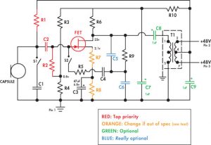
Schematic
The 219 and 319 printed circuit boards
The design of these mics has changed a lot over the years, and you’ll find that there are four basic PC board layouts. The third and fourth match the schematic shown here.
Revision 1: You can tell the first type of board because the capsule leads are soldered directly to the PC board without any standoffs. Board traces go from the FET to C2 capacitor and to the capsule. C7 on the schematic is replaced with three 1 uF capacitors in series.
Revision 2: This layout uses plastic standoffs to which the capsule wire, C2, and the FET are soldered. This results in lower noise and less trouble with flux contamination. This board can be recognized because C7 is replaced with three capacitors in series but there are standoffs on the front end.
Revision 3: This layout matches the schematic exactly. There is one capacitor for C7, but the reed switches (glass barrel things) are still mounted directly to the rear of the PC board. Most of the mics out there seem to be this revision.
Revision 4: This board does not have the reed switches on the main PC board but has a small daughterboard with the reed switches on it. Avoid this revision if you can, and if you can’t, remove the daughterboard—and therefore the pad and bass-cut functions.
There may be other variations on the electronics out there that I have not seen, so keep your eyes open. Revision 3 and Revision 4 boards may sometimes be seen with plastic FETs instead of metal-can FETs.
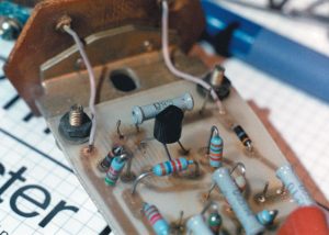
Type 1 board
How the electronics work
The electronics are comparatively simple. They consist of a single FET that acts as an impedance converter stage, and a transformer that takes care of balancing the output.
Power is supplied on the output jack by the preamplifier, so pins 3 and 7 of the transformer are about 48 V above ground. This means that the center tap of the transformer is also 48 V above ground, and the DC offsets on both sides of the transformer cancel each other out so the transformer doesn’t saturate. So we take the power off the center tap, use C9 to filter any noise or residual signal from it, and then apply it through R1, a very high value resistor, to directly polarize the capsule. We also run it through R10 and C7 to produce a lower filtered voltage that is used to power the front end.
With 48 V charging the capsule up through the very high value resistor, any change in the capsule capacitance will result in a change of voltage on the output because it changes the amount of charge the capsule stores. This is dependent on the resistor being such a high value that it only very slowly affects the capsule charge. The changing voltage across the capsule is read through C2 (which blocks the DC polarizing voltage), and into the input of the FET.
The pad operates by shunting an additional fixed capacitor, C1, across the capsule. This means that the output is reduced, because the total change in capacitance is much smaller compared with the total amount of capacitance there. I don’t really like this method of padding but it’s one that a lot of manufacturers use.
R3 and R4 are a voltage-dividing ladder shunted between ground and the rail voltage. They are used to generate a fixed DC voltage to set the FET bias through R2, another very high-value resistor, so that the FET is just slightly turned on at all times with no signal in the mic.
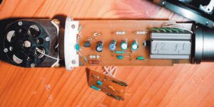
Type 3 board (1)
The FET turns on and off with very tiny changes in the gate voltage. When it turns on, current flows through R6, through the FET, then down through R7 and R8 to ground. Now, the Russian folks designing this thing have done some interesting tricks to compensate for differences in the FETs. R8 is bypassed with a capacitor, and signal can go through the capacitor easily, so adjusting R8 only affects the DC level on the source of the FET. R7 affects both the DC level and the AC level, though. So the factory will drop in different values of R7 and R8 depending on the turn-on voltage and the gain of the FETs they are using on any given day. Since we’re going to be replacing the FET with a much more consistent device, these values are going to be changed to stock ones.
When the FET turns on, it reduces the voltage on the bottom of R6 by pulling it toward ground. So the voltage on the base of R6 is going to be proportional to the amount of movement of the capsule. We block the DC on it with C8, and apply it to the primary of the transformer. The transformer secondary, then, carries that signal out to the microphone preamplifier as a balanced signal.
R5, C4, C5, and R9 make up a low-pass filter network connected to the FET output. When the low-cut switch is turned on, the low-end signal is applied to the FET gate. Since the FET stage is inverting, this means the low-end feedback reduces the low-end response of the system and drops the bass response. This doesn’t seem to me like a good way of doing a bass cut, since it also results in the load on the capsule changing and so it can alter the high frequency response as well.
That’s how it works… now what do we change?
The whole goal of the microphone design is to make sure there is as high as possible an input impedance so the capsule sees as little loading as possible, and to make sure there is as low an output impedance as possible so the transformer loads the FET stage as little as possible. Our goal for these modifications is to make this actually be the case.
First of all, if you encounter any of the Revision 4 boards, remove the daughter board completely and discard it. On these boards, C1, C4, and R5 and the switches for the bass cut and pad are on the daughter board, and by removing the board you lose the bass cut and pad functions. However, removing all of the additional stray wiring which substantially contributes to stray capacitance is essential. If you have a Revision 4 board, you’ll have to live without the bass cut and pad functions (which is not a terrible loss since they both degrade sound quality when used anyway).
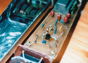
Type 3 board (2)
Front-end components
The most substantial sonic changes can be made by upgrading all of the parts in the front end. Desolder the FET, the capacitor C2, and the two resistors. Replace the two resistors with 1000 Megohm types. The original resistors are specified at 500M ohms but often substantially lower values can be found in these mics, especially in earlier production. Replacing them with 1000M types will substantially improve the top and bottom end response. Likewise, replacing the 680 pF blocking capacitor C2 with a higher-grade COG type of slightly larger value will improve linearity a lot. The original capacitors use a poor grade of dielectric that results in higher distortion.
Replace the FET with a Toshiba 2SK170BL according to the photograph of the modified Revision 1 board. The original FETs have different pin configurations and come in several variants; you want the center pin of the new FET to be connected to C2 and the other two pins to be connected to the resistors R6 and R7. As long as the flat side of the FET goes toward the capsule, the center pin is connected to C2, and the ground hole is unused, you are fine. Many of these boards come with four-pin metal-can FETs in which the fourth pin is connected to the can of the FET and goes to a hole on the board that is grounded. You can see in all of the photos that these holes are left disconnected on boards using plastic FETs, and we wish to leave them disconnected when we install a new FET.
Because such a huge variety of different FETs were used at Oktava, resistors R8 and R7 are normally selected for each particular FET, as mentioned above in the circuit description. With the 2SK170, we want to have R8 be 2.0K and R7 be 1.78K. Check the resistors in place on your board and if you see something different, replace them with precision 1% types. If you have any question, measure between the junction of R7 and the FET and the junction of R4 and R2; this is the bias voltage being applied to the FET and it should be approximately 1.3V.
Capacitors
Replace all of the cheap electrolytic capacitors with tantalum types. That is, C7, C8, and C9 should be changed from poor-quality 1uF aluminum electrolytics to higher-grade tantalums.
If you encounter a Revision 1 or Revision 2 board where C7 consists of three 1 uF caps in series, replace two of those capacitors with wire jumpers and one of them with a 4.7 uF cap. It is possible, as you can see in the photo of the modified Revision 2 mic, to replace this set of three with a 1 uF mylar film capacitor, and this may bring a slight sonic improvement. Sadly, the one capacitor that would really benefit from replacement with a film cap is C8, for which there isn’t much room. The problem with the film capacitors is that they are substantially larger than electrolytic types.
You could decide to replace C1, C4, C5, and C6 with higher-grade ceramic capacitors, which will improve the quality of the sound when the pad or bass-cut switches are enabled. Unfortunately, I think it does not improve the sound enough for me to ever want to use the pad or bass-cut functions, so I normally just leave them alone. You could make some argument that C5 and C6 are in the signal path even when the bass cut is not engaged, so you might consider replacing them. I don’t hear a substantial improvement with replacing C5 and C6 but it’s not much additional work, so I’ll leave that up to you.
Conclusion
The Oktava 219 and 319 microphones have well-designed and solid electronics and quite fine capsules. Unfortunately the quality of construction and the case designs sometimes leave something to be desired, but I think all of the changes suggested in this article are well worth the effort and can improve a good microphone quite considerably.
Scott Dorsey ([email protected]) is a recording engineer and electronics engineer in eastern Virginia.
Parts Lists
—————————————————————————————————————-
Electronics
Parts / Quantity / Description / Digi-Key Part
—————————————————————————————————————-
C7, C8, C9 3X 4.7 uF 50V tantalum P2077-ND
C2 1X 820 pF COG ceramic P4860-ND
C3 1X 100 uF 6.3V tantalum P2019-ND
R1, R2 2X 1000M (1G) resistor MOX200J-1000MEG-N
Possibly needed:
R7 1X 1.78K 1/4W film resistor 1.78KXBK-ND
R8 1X 2.00K 1/4W film resistor 2.00KXBK-ND
C5 1X 1500 pF COG ceramic P4863-ND
C6 1X 680 pF COG ceramic P4859-ND
1X Toshiba 2SK170BL FET (not available from Digi-Key)
You might want…
Chemtronics flux remover pen CW9100
Paladin solder sucker PAL1700-ND
—————————————————————————————————————-
All electronics parts except the FET are available from Digi-Key at 1-800-DIGI-KEY.
You will need to purchase window screening and silicone compound at a local hardware store.
Chemtronics Flux Remover spray and GC Electronics conformal coating are available from Cain Electronics in Hampton, VA, at 757-826-5535. They also sell silicone RTV.
The specified Toshiba 2SK170BL FET is sometimes available from B+D Enterprises (800-458-6053 or http://www.bdent.com) or MCM Electronics (800-543-4330 or http://www.mcmelectronics.com). They both have a minimum order and do not always stock the 2SK170BL (and no, other 2SK170 variants won’t work).
I will personally sell 2SK170BLs for $5 each postpaid for a check or money order sent to:
Kludge Audio
Box 1229
Williamsburg, VA. 23187
You should know that this is considerably more than the going rate and the parts I am selling aren’t any better than anyone else’s. I don’t want to be in the business of selling parts but I understand that some of these are difficult to get so I am doing this as a service if you have no alternative.
Sidebar: The 219/319 Capsule Baffles—Strictly Optional!
The Oktava capsule is built with a black metal baffle with eight holes screwed to each side of the capsule. This forms a resonant chamber on each side of the diaphragm and increases the high-
If you remove these baffles, you will get a smoother but a more rolled-off top end. If you use the mics on vocals, you may prefer the sound with the baffle in place. If you use it on horns, you may prefer the sound with the baffle removed.
I don’t recommend removing the baffle the first time around, and I suggest being very careful working around the capsule if you decide to remove it. You will have to desolder the ground lead from the board which is wired to the center post on the diaphragm to remove the baffle; don’t attempt to solder or desolder to the center post because it’s very easy to overheat it and damage the capsule.
Removing the baffle will change the sound, but whether it improves it or not is a matter of taste and application. I include mention of this change here because it’s a useful thing to know about, not because I strictly recommend doing it on all microphones.