A retrofit upgrade for many Chinese mics
By Scott Dorsey
“Shanghai Mike is known all along the Yangtze for his dastardly ways.” —AjD, not Warren Zev
There is a large number of manufacturers currently selling large-diaphragm microphones from Chinese OEMs, and a large number of them are made at one Shanghai factory that produces a few variations on a standard design. A lot of other companies are importing the cases and bodies from the Shanghai factory and dropping in their own electronics. Still more companies are buying from other Chinese manufacturers that have bought tooling from the Shanghai factory or have copied their tooling.
As a result, there’s a wide variety of very similar microphones on the US market, with wide variations in construction quality and sound quality depending on how they were made and for whom—and to some degree on the US company you buy from and how much you pay.
The same retrofit described in this article will work in all the mics that are designed around the Shanghai U87-like body and the Shanghai U87-like capsule. Will it turn a $99 mic into a Neumann U87? Of course not, but it will improve the sound considerably in many cases.
But not in all cases! And now we get to the disclaimers. Some mics built around this model, like the ones sold by Langevin and Groove Tubes, aren’t going to benefit from this mod—their electronics are already “upgraded,” and this mod will probably do much more harm than good.
Furthermore, on some models you will lose some features. If your mic has the optional bass cut, either internal or external, you’ll lose that. If you have the 10 dB pad, you’ll lose that (and that’s no loss, since with the new electronics you’ll be able to get a much higher level into the mic before clipping it, even without the pad). If you have one of the dual-diaphragm models that give you an omni and a cardioid pattern, you will lose the pattern adjustment (and that is a substantial loss, I admit).
As you might expect, assembling a comprehensive list of mics that use these capsules wasn’t easy, and I’m pretty sure I’ve missed a few. But the sidebar ‘ ;So Who Sells These Mics, Anyway?’ will at least get yo u started on determining if that slick new mic you just bought at your local store might benefit from this mod.
If your model isn’t listed, consult the photo on page 68—if your mic’s innards look like this, the mod should work. And as always, remember that you’re voiding your warranty, that the manufacturer won’t service your mic any more, and so on.
The design
If you read my ‘What’s in a Mic’ article from 9/01, you’ll find this mic design very familar indeed. But unlike the Panasonic capsules, which are electrets that have built-in FET impedance converters, these capsules require an external polarization voltage to charge them up.
Since they don’t have an integral FET, we have to supply one. And because we are building the impedance converter, we have some circuitry on the board that has very, very high impedance and must be kept extremely clean to prevent any grease or residual flux from forming slightly conductive paths on the board and increasing the noise floor.
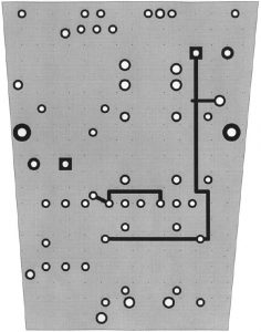
PCB top (dot grid spacing = 0.1″)
The general circuit design is adapted from one that was originally invented by Schoeps but has been used in variations for several decades now. It’s a very ingenious little arrangement. Many thanks to David Josephson, who originally introduced me to it.
The thing about phantom power is that it provides 48V on the microphone input, and the key to using phantom power is figuring out how to derive all the internal voltages for the microphone from that. For example, we need a high voltage to polarize the capsule. R7 and R8 allow phantom power to pass through.
Now, since all the signal is differential between the two output pins, it should all cancel out. But if it doesn’t, C5 smooths out any residual noise on it, giving us a nice clean voltage that is somewhere around 35V. (Some voltage is lost through R7 and R8, and more importantly the 48V input is pulled down to a lower voltage when it’s in operation).
R9 is a very, very high value resistor that allows only small amounts of that polarization voltage to reach the capsule. We need a very high value here to prevent as much signal as possible from being lost.
With that charge across the microphone capsule, vibrations will change the capacitance of the capsule and the amount of charge it stores will change, so the voltage measured at the input pin will change. Our whole goal here is to measure those changes.
The input amplifier stage is Q3, a FET with a very high impedance input. Now, the FET wants to see a negative voltage on the input gate in normal operation. Since we don’t have a negative voltage supply, what we do is we make sure the gate is sitting at about ground level with R10, we couple the input into the FET gate with C6, which blocks all DC, and then we lift the other pins of the FET up to a positive voltage so the gate is negative when it’s idle.
We supply 12V DC from the 12V supply (more about that in a second) to the drain of the FET through R1, a 2.2K resistor, but then we also have another 2.2K resistor R2 to ground. Since there are a few volts of voltage drop across R2, it keeps the source of the FET a few volts above ground and so the gate is a few volts below it.
The whole thing about the FET is that as the voltage on the input changes, it allows more or less current to flow through it. So if there is a high level pulse sent in from the capsule, it will pull the source and drain voltages closer to one another. A positive pulse in the input makes it conduct more, causing the voltage at the input of C3 to become higher and the voltage at the input of C2 to become lower. These two capacitors allow us to block those DC voltages, and if we looked at the other end of them, we’d see two AC signals that were exactly the opposite of one another, which is just what we need to drive the output.
But while I told you where the 35V supply for polarizing the capsule came from, I didn’t tell you where the 12V supply came from. I’m not going to tell you about that yet, either.
We’ve got these two opposing voltages, and we need a little bit of amplification to bring them up to mic level. And we need some way of coupling them into the output, which has 48V on it. This can be done with a pair of bipolar transistors.
While a FET turns on with an applied voltage, a bipolar transistor reads the current on the input to turn it on. This means it’s not of much use in a circuit that needs a high input impedance, but it’s got some other advantages, like being easier to bias. Since we already have 48V on pins 2 and 3, all we need to do is pull those voltages down a little bit when we want to send a signal, so we send them through a pair of bipolar transistors which act as shunts to ground.
We could tie the collectors of the transistors to ground, put R4 and R5 on the bases so they’d always be just a little bit turned on (which is what class A operation means), and then when there was a pulse on C2 it would cause Q1 to conduct and pin 2 would be pulled down, while the opposite pulse on C3 would cause Q2 to conduct less and pin 3 would be pulled up. This gives us our differential output.
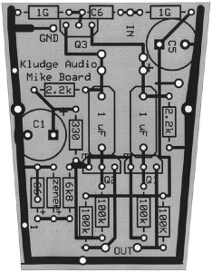
Parts layout
But we’ve got a lot of current going through these transistors when they are idle, so we need to stick a 6.8K resistor, R6, between the collectors and ground so they don’t sink too much current when they are idle. And, hey, while we’re doing that we can stick a zener diode in series there.
The zener diode is a nifty device. It’s like a resistor whose value always changes to make sure it has a constant voltage across it. So we have a 12V zener between R6 and ground, and it changes value to make sure that it always has 12V across it. This doesn’t affect Q1 and Q2 much at all, but it means we now have a very convenient source of 12V power for the input stage.
See, I said I’d tell you where that 12V supply was. It’s actually part of the collector circuit on the output stage. C6 is bridged across the zener because the zener actually produces a lot of noise and the capacitor smooths it out. R3 and C1 together make an additional filter network to smooth out the last bit of noise for the sensitive input stage, and they supply power to the input stage through R1.
So the circuit that keeps the output stage above ground also provides power for the input stage. The direct voltage across the output stage provides power to polarize the capsule.
The input stage not only acts as an impedance converter to take the very high impedance input from the capsule, but it also acts as a splitter stage to turn that input into two opposing inputs. The output stage acts as an amplifier, giving both voltage gain and current gain to drive the output, and it uses the impressed voltage on the output as its own power supply, while also generating the voltage for the input.
Everything is very tightly interconnected, and each stage is doing several things at the same time. That’s why I claim this circuit is just so incredibly ingenious. I want to meet the man who invented it.
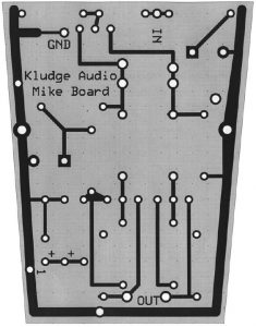
PCB bottom
Building it
First, stuff the board. This is not all that easy to do since the board is rather tightly packed, but the layout diagram is fairly self-explanatory and should show you how to do it. Make sure you put the transistors, the zener diode, and the tantalum capacitors in the correct way. The stripe on the zener diode goes away from ground.
Second, deflux the board. This is critical! Even a tiny amount of residual flux left on the input section of the board will increase the noise floor. Spray the board thoroughly with Chemtronics Flux-Off, then turn it around and do it again. Yes you can use 98% isopropanol and a Q-tip and a lot of elbow grease and probably get the same result, but Flux-Off is easier and more certain. If you do it by hand, make especially certain that there is no residue around the input section of the board where the FET and 1GOhm resistors are.
Third, unscrew the base of the microphone, remove the four screws holding the PC boards in, remove the existing PC boards, and carefully desolder the leads to them. Unscrew the six Phillips screws holding the transformer can at the bottom of the chassis, remove the transformer, and put those screws back in.
Now you have an open chassis frame with a grey wire and a brown wire coming from the capsule, red, red/white, and black wires coming from the XLR connector in the base, and if your model has them, wires from the pad and external high pass switches (which you should tape out of the way or cut off, since these features won’t be implemented).
Incidentally, you should be very careful removing and inserting these screws, because they are very soft and inexpensive metal and they can easily be stripped or twisted off. If they don’t go in easily, loosen some of the other screws a bit and put a dab of lubricating oil on the ones that seem to be binding.
Screw the new board into place using two of the screws you removed when taking out the old boards. Connect th e grey wire from the capsule to the ground pin on the board; this is the stator lead and is connected to the side of the capsule. Connect the brown wire from the capsule to the IN point on the board; this is connected to the center point on the capsule diaphragm.
The black wire goes to pin 1 on the XLR connector and should be hooked to the point on the board marked 1, which is a ground. The red wire and red/white wire should be hooked to the points marked 2 and 3 respectively.
Once again, now deflux it. Use the long nozzle on the Flux-Off spray to clean off the connections you made. Be very careful not to get any of this stuff near the capsule.
Screw the base back together again and give it a listen! If you hear a lot more noise than you think you should hear, give it another hit with the flux remover and wait a few minutes for it to evaporate. Because the circuit is so high-impedance, it does not take much residual flux or atmospheric condensation to bring the noise floor way up!
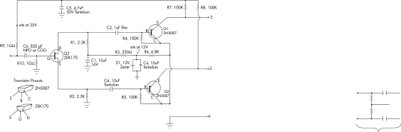
Schematic
If you can get a conformal coating, coat the board with it; if you can’t, don’t worry about it. The urethane conformal coats seem to be the most reliable for this sort of application, but one bottle will do a huge number of boards. If you aren’t doing a lot of boards, don’t sweat it unless you’re in a high humidity environment.
The overall sound is much better with the retrofit board, with a lot of the problems in the low end going away. (There is still a very large peak around 6K that varies in exact frequency from unit to unit. That’s due to the capsule, and I considered trying to filter it out but the fact that it varies so much makes this difficult, and all in all it’s part of what makes the sound of the mic anyway.) I think you’ll find this mod an enormous improvement.
Scott Dorsey can be reached via [email protected]
Sidebar 1: So who sells these mics, anyway?
There are many companies importing and selling microphones from the Shanghai factory, or microphones which are built with their standard design and tooling. I have attempted to list a few of the ones that are available, and which this board should fit into. I have omitted all of the tube microphones which are also made by the Shanghai people, in part because I have not used those microphones and don’t know what the internal design is like. So consider this a list of a few of the Shanghai-type FET microphones:
ADK A51 — Cardioid, bare bones
ADK A51S — Cardioid, pad, internal high pass
ADK A51SD — Dual pattern, pad, internal high pass
Audix CX-101 — Cardioid, bare bones
Audix CX-111 — Cardioid, pad, internal high-pass
Audix CX-211 — Cardioid, pad, external high-pass and yoke
Avlex AVS77 — Cardioid, pad and external high pass and yoke
Avlex AVS79 — Cardioid, internal high-pass
Avlex AVS80 — Cardioid, pad, external high-pass
NADY SCM 900 — Cardioid, bare bones
NADY SCM 910 — Cardioid, with pad and external high pass
NADY SCM 920 — Dual pattern, with external high pass
NADY SCM 980 — Cardioid with pad and external high pass (Note: I have not inspected the SCM980. The NADY SCM1000 is definitely
different and this board will not fit in it.)
Soundking SKEB001 — Three pattern with 10 dB pad
Soundking SKEB002 — Cardioid with external high pass and external 10 dB pad
Soundking SEKB006 — Cardioid with internal low cut
Stagg MCO-7BK — Dual pattern with (internal) high pass, 10 dB pad (sold in UK)
Yorkville APEX 420 — Dual pattern with (internal?) high pass
Yorkville APEX 430 — Bare bones cardioid
Now, Marshall says that their mics aren’t made by the Shanghai factory at all but are made in their own factory, but the board configuration is identical and so you should be able to use this retrofit board in their mics as well:
Marshall MXL2001P — Cardioid, bare bones (some have internal bass cut)
Marshall MXL2002 — Cardioid, three-position switch for bass cut, 10 dB pad
Marshall V67G — This is a stripped-down cardioid mic with a different case. Even though the case is different, the board size is the same. (The Marshall MX2003, V77, MXL600 are very different)
The Langevin microphone is also not made at the Shanghai factory but the case and capsule seem to be made on the same model. However, the electronics inside are of Manley’s design and a huge improvement over the stuff in the microphones above; I suspect that this retrofit will degrade rather than improve them:
Langevin CR3A — Cardioid, 10 dB pad, external bass cut
The PMI Joemeek “Meekrophone” and the Behringer B-2 are definitely not Shanghai mics at all and this board will not fit them, although the board they use is larger and it may be possible to cut to fit. The Studio Projects microphones come from the Beijing factory and also have different boards. This board will not fit the BPM Studiotechnik mics either (for some reason, several folks have asked me about that).
The Groove Tubes FET microphones are also made in China but they are made on a different pattern and with totally different electronics. However, because they are designed to handle large, well laid-out PC boards unlike the majority of the Chinese mics, it might be possible to fit these boards into place with some mounting. On the other hand, these microphones have substantially better electronics than the microphones listed above and might not benefit at all from the retrofit.
Some folks have asked me if they will fit the Brand-X X21F condenser mics, but quite frankly I cannot find any information at all about these microphones. Should you find out what they are, please let me know in care of the publishers ([email protected]).
Many thanks to Brent Casey at Marshall, EveAnna Manley at Manley Laboratories, Aspen Pittman of Groove Tubes, Xiaocong Guo, Wang Zheng, and David Josephson of Josephson Engineering. Thanks also to an anonymous personal contact who let me take apart his NADY mics.
Sidebar 2 Parts list:
The part numbers on the righthand side are from Digi-Key corporation, at 1-800-DIGI-KEY. Note that the resistor values used are slightly different than those listed on the schematic because they are standard 1% values. You can try Cain Electronics of Hampton, VA, at 757/826-5535 for GC Print-Kote conformal coating and for Flux-Off flux remover (in a spray can rather than a pen).
I am selling a kit that includes the Toshiba 2SK170BL FET and the PC board for $20, postpaid. Send your check or money order to:
Kludge Audio
PO Box 1229
Williamsburg, VA 23187-1229
If you don’t want to pay me for ’em, the layouts for the boards are printed here so you can make your own, but you are on your own for finding the FETs in small quantity. B&D; Enterprises occasionally has them but does not have a consistent supply.
Q1, Q2 2N5087 transistors 2N5087-ND
Z1 12V zener diode 1N5242BDICT-ND
C1, C4 10 uF 16V tantalum cap P2038-ND
C2, C3 1uF 100V film caps EF1105-ND
C5 4.7 uF 50V tantalum cap P2077-ND
C6 820 pF COG ceramic capacitor P4860-ND
R1, R2 2.21K resistors 2.21KXBK-ND
R3 332 ohm resistor 332XBK-ND
R4, R5, R7, R8 100K resistors 100KXBK-ND
R6 6.8K resistor 6.81KXBK-ND
R9, R10 1000M (1G) resistor MOX200J-1000MEG-ND
Chemtronics flux remover pen CW9100